
[日本語] / English
Related Hack -> Make the AVRISP mkII Clone from Arduino Leonardo / Micro
I tested and confirmed function of this hack on only “avrdude ver 6.2”
1. Introduction
It will be able to make the AVRISP mkII clone if you a little modifying to Arduino UNO / Leonardo / Micro PCB.
Below is an article on making Arduino UNO Rev.3 into AVRISP mkII clone.
2. How about a little modifying
- Burn the firmware of AVRISP-mak2 clone to the USB-Serial chip ATmega16U2 of Arduino UNO Rev.3. And it works as AVR-programmer.
- The signals (RESET, SCK, MISO, MOSI) required for ISP-programming can be derived from J2 and ICSP pins.
- The signals (RESET, TPIDATA, TPICLK) required for TPI-programming can be derived from J2, D0, D1 and TX-LED line (inner of PCB).
3. Prepare these
- Arduino UNO Rev.3 (type of ATmega328P DIP28)
Also we can use UNO R3 compatible board (equipped with ATmega16U2, JP2, ATmega328P DIP28). - Windows PC. But Windows10 is not supported.
- “Flip” tool
DFU-Programming software。Download it below URL of Atmel’s Flip-webpage. And install it.
http://www.atmel.com/tools/FLIP.aspx
“Flip” dose not run under the Windows10. - AVRISP mkII clone firmware
AVRISP-MKII_ATmega16u2.zip After decompressing “AVRISP-MKII_ATmega16u2.hex” is appeared. - Header pin 3×2(2.54mm pitch) .
4. Removing the ATmega328P
- We do not use ATmega328P on Arduino UNO board, so remove it. ATmega328P removed will be kept safe. It is necessary when returning original Arduino UNO.
5. Modifying the PCB
- Adding header-Pins
- Cut the solder side of the two pins of the 3x2header-pin. Fig.1
- Check the JP2 pad on your Arduino UNO R3 board. Fig.2, 3
- Remove the solder of J2 pad. Fig.4
- Solder the 3x2header-pin to JP2. Fig.5
- Wiring to get TPICLK
Soldering the thin wire from TX-LED to J2 3x2header-pin. Fig.6
Figures, click to enlarge.
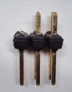 Fig.1 Cutting Fig.1 Cutting |
 Fig.2 Location JP2, 16U2 Fig.2 Location JP2, 16U2 |
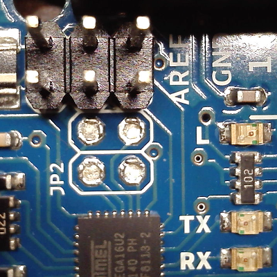 Fig.3 JP2 Fig.3 JP2 |
 FIg.3 Removing solder FIg.3 Removing solder |
 Fig.4 Soldering 3x2Header Fig.4 Soldering 3x2Header |
 Fig.5 Wiring Fig.5 Wiring |
5. Start DFU-loader
- Set the short pulg
Short the No.5 with No.6 pins on ICSP of ATmega16U2. Fig.6 Fig.6
Fig.6 - Connect to USB
Connect Arduino UNO to USB port. And after, remove the short-pulg 5 with 6 on ICSP of ATmega16U2.
ATmega16U2 run on DFU-mode. - Install Driver
Windows detect new USB device”Atmel Corp IOUSBHostDevice”(or ATmega16U2 DFU). and install drivers.
There are drives file in the folder as below.
C:\Program Files\Atmel\Flip 3.4.7\usb\
6. Burn the AVRISP mkII clone firmware
- Launch the Flip tool and burn the AVRISP mkII clone firmware.
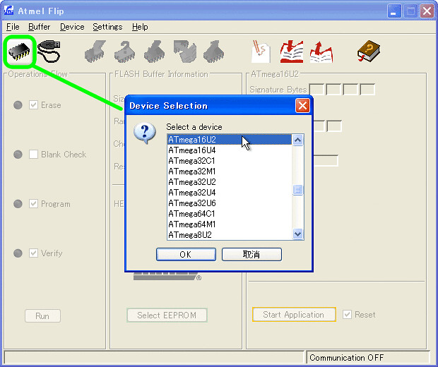
Figures 2 to 5 show how to write other firmware to ATmega16u2.- Select ATmega16U2 (Fig.7)
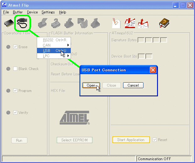
- Open with USB connection (Fig.8)
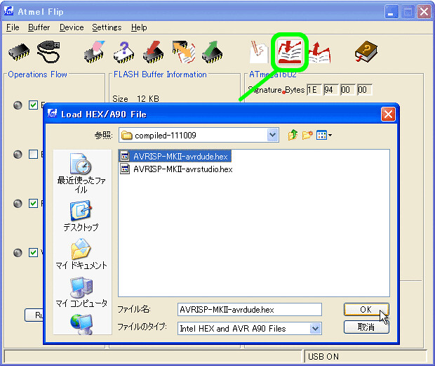
- Load AVRISP-MKII_ATmega16u2.hex . (Fig.9)
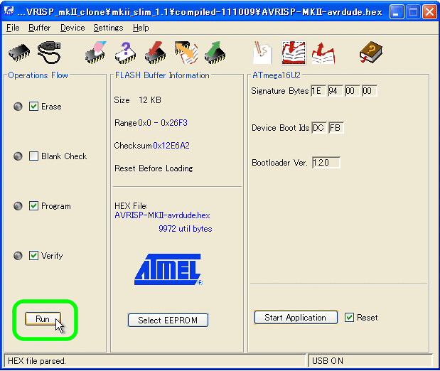
- Click [RUN] = Burn (Fig.10)
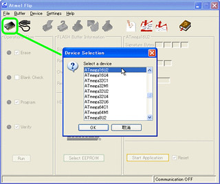
Fig.7
Fig.8
Fig.9
Fig.10
7. Recognition of AVRISP mkII
- Disconnect the USB cable and reconnect it.
- When reconnecting, the USB device ATMEL AVRISP mkII appears.
- If the device driver is required, install “libusb” generic USB driver. How to install it (google search)
8. Arduino UNO R3 AVRISP mkII signals
| ISP mode | TPI mode |
 |
 |
9. How to return to the original
- Run the DFU-mode on ATmega16U2
- Launch the Flip-tool.
- Burn the USB-Serial firmware below.
C:\Program Files\Arduino\hardware\arduino\avr\firmwares\atmegaxxu2\UNO-dfu_and_usbserial_combined.hex - Insert ATmega328P to socket.(to fit the notch device and socket)
another Related Hack -> Burning the Bootloader without external AVR-Writer on “Arduino UNO Rev.3”
update 2016.01.13 AVRISP mkII Clone firmware version up
upload 2017.01.04 (c) by Kimio Kosaka

