- 概要
- Arduinoもくもく会#017に参加しRaspberry Pi上のArduino IDE にmicro:bit開発環境を構築するテーマに取り組みました。
- その成果を整理して,Arduino IDEのボードマネージャからインストールできるようにしました。
- ただし,ボードマネージャからのインストール操作に加えてapt-getによる開発ツールの手動インストールも必要です。
- Intel-CPUのパソコン(Win,mac,Linux)のArduino IDEにmicro:bit開発環境をインストールする方法はこちらを参照→https://ht-deko.com/arduino/microbit.html
- インストール手順
- micro:bit–nRF5用のgccコンパイラとhex書き込みツールopenocdをapt-getによりインストールします。
$ sudo apt-get install gcc-arm-none-eabi openocd - Arduino IDE の「ファイル」→「環境設定」と開き「追加ボードのURL」欄に下の直接リンクURLをコピーしペーストします。
https://kimio-kosaka.github.io/RasPi_Arduino_nRF5/package_nRF5_boards_index.json - Arduino IDE の「ツール」→「ボード」→「ボードマネージャ」と進み,ボードマネージャの最下段あたりにあるNordic Semiconductor nRF5 Boards for Raspbian by Sandeep Mistry/modified by Kosaka.Lab.をインストールします図1
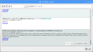 図1
図1 - インストール中に警告が出ますが想定内のモノですので無視します。図2
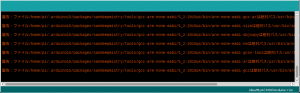 図2
図2
- micro:bit–nRF5用のgccコンパイラとhex書き込みツールopenocdをapt-getによりインストールします。
- スケッチのコンパイルとアップロード
- 図3のようにボードの設定をします。
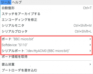 図3
図3 - 下のサンプルスケッチ(https://ht-deko.com/arduino/microbit.htmlから引用)をコンパイルしアップロードするとLEDマトリクス上を輝点が走ります。
const uint8_t max_cols = 9;
const uint8_t max_rows = 3;
const uint8_t cols[max_cols] = {3, 4, 10, 23, 24, 25, 9, 7, 6};
const uint8_t rows[max_rows] = {26, 27, 28};

typedef struct TPoint {
  uint8_t x;
  uint8_t y;
} POINT;

const POINT ledpos[5][5] =
{
  {{0, 0}, {3, 1}, {1, 0}, {4, 1}, {2, 0}},
  {{3, 2}, {4, 2}, {5, 2}, {6, 2}, {7, 2}},
  {{1, 1}, {8, 0}, {2, 1}, {8, 2}, {0, 1}},
  {{7, 0}, {6, 0}, {5, 0}, {4, 0}, {3, 0}},
  {{2, 2}, {6, 1}, {0, 2}, {5, 1}, {1, 2}}
};

void led_init() {
  for (int i = 0; i < max_cols; i++) {
    pinMode(cols[i], OUTPUT);
    digitalWrite(cols[i], HIGH);
  }
  for (int i = 0; i < max_rows; i++) {
    pinMode(rows[i], OUTPUT);
    digitalWrite(rows[i], LOW);
  }
}

void led_pset(const uint8_t x, const uint8_t y, const uint8_t mode) {
  POINT position = ledpos[y][x];
  digitalWrite(cols[position.x], !mode);
  digitalWrite(rows[position.y], mode);
}

void setup() {
  led_init();
}

void loop() {
  for (int y = 0; y < 5; y++) {
    for (int x = 0; x < 5; x++) {
      led_pset(x, y, HIGH);
      delay(300);
      led_pset(x, y, LOW);
    }
  }
}
- 図3のようにボードの設定をします。
- 発展(自分用メモ)
- Arduino IDE + micro:bit の活用はココ↓が秀逸
https://ht-deko.com/arduino/microbit.html - micro:bitに用いられているnRF51822チップを単体(ブレークアウトボード付)で入手可能→太陽誘電小型BLEモジュール基板
- このモジュールはArduino IDE でGeneric nRF51を選択してコンパイルとスケッチのアップロードが可能
- 単体nRF51822へスケッチのhexを書き込むためには「ST-Link」を使う
Aitendo ST2/ST32ライタ Aliexpless ST-Link
NucleoボードのST-Linkも使える
- Arduino IDE + micro:bit の活用はココ↓が秀逸
How to make
MENU
Raspbery PiのArduino IDEにmicro:bit開発環境を構築する
- HOME »
- Make »
- Electronic Work »
- Raspbery PiのArduino IDEにmicro:bit開発環境を構築する


