When we burn the bootloader of Arduino Diecimila, we connected external AVR-Writer to ICSP of Diecimila.
But I found the method to burn the bootloader by Diecimila itself without external AVR-writer.
It is able to do by FT232RL BitBang Mode AVR-Writer software.
And, this method is usable on the Arduino NG, Arduino Duemilanove and w/ATMega328P too.
But, this method cannot do on the Arduino Uno.
Japanese English
This page was renewed for tutorial of "Btibang method" in GUI-Operation.
Old version tutorial in CUI-Operation is here -> Burning the Bootloader without extarnal AVR-writer (CUI Operation)
How to run this "FTDI Bitbang method" with the Arduino-IDE ->Click here
- FT232RL BitBang Mode AVR-Writer
FT232RL is an USB-Serial bridge on an Arduino Dicimila/NG/Duemilanove PCB. It has the function to manipulate each signal pin directly.
It's called BitBang Mode.
"avrdude-serjtag" is AVR-Writer software developed by Mr.Suz. It include the function to control FT232RL BitBang Mode.
If we use "avrdude-serjtag" we can burn the bootloader by Diecimila itself.
I describe below the method. on Windows-XP.
- Attention!!!
If you want use "avrdude-serjtag" on Linux or Mac OS, you must remake ( patch, reconfigure and recompile) it.
There are useful projects.
-
These projects made a way to BitBang Mode AVR-Writer on Linux and Mac !!!
Of course, if you use Windows in Vmware on your Linux or Mac OS, you can run "avrdude-serjtag(windows version)".
avrdude by FT245R/FT232R(Linux) (Translated to English by Google.)
FTDI Drivers for avrdude in Linux by Coffeebot Labs
BitBang Mode AVR-Writer on Mac (Translated to English by Google.)
- Modify the Dicimila
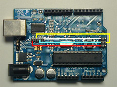
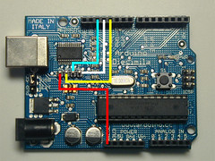
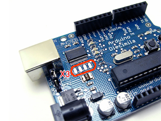
There are four pads written as X3 near FT232RL on a Diecimila PCB.
(These pads are connected to the control pins of FT232RL.)
Remove the solder of these pads and insert a pin-header. And soldering it.
- Downloading
- "avrdude-serjtag" FTDI BitBang AVR-Writer
serjtag-0.3.zip mirror site
serjtag-0.3.tar.gz mirror site
- serjtag-0.3.zip original site (http://suz-avr.sblo.jp/archives/20070621-1.html)
serjtag-0.3.tar.gz original site (http://suz-avr.sblo.jp/archives/20070621-1.html)
- configure-file for avrdude-serjtag
avrdude.conf (Update: included chip-parameter of ATmega328P,168P and 88P)
- "avrdude-GUI (yuki-lab.jp Version)" GUI wrapper for avrdude
avrdude-GUI-1.0.5.zip mirror site
avrdude-GUI-1.0.5.zip
original site (http://yuki-lab.jp/hw/avrdude-GUI/index.html)
- avrdude-GUI (yuki-lab.jp Version) require Microsoft .NET Framework 2.0.
When .NET Framework 2.0 is not installed. Download it from
here (Microsoft .NET Framework 2.0 download page) and install it.
- Installing
- avrdude-serjtag
- Exract serjtag-03.zip.
- Copy "avrdude-serjtag" folder into the "C:\Program Files" folder.
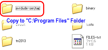
- Delete "src" folder in the "avrdude-serjtag" folder.
- avrdude.conf
- avrdude-GUI (yuki-lab.jp Version)
- Extract avrdude-GUI-1.0.5.zip.
- Copy "avrdude-GUI-1.0.5" folder into "C:\Program Files" folder.
- avrdude-GUI (yuki-lab.jp Version) require Microsoft .NET Framework 2.0.
When .NET Framework 2.0 is not installed. Download it from
here and install it.
- Setting
Open the "C:\Program Files\avrdude-GUI-1.0.5" folder.
And double click the "avrdude-GUI.exe" to run it.

"avrdude-GUI" settings is as below from i to iv.

- avrdude.exe File area
- Click on the
 .
.
- Open "C:\Program Files\avrdude-serjtag\binary" folder.
- Select "avrdude.exe", and click on the [Open(O)] button.
- Programmer area
- Click on the
 .
.
- Select "FT232R Synchronous BitBang (diecimila)".
- Device area
- Click on the .
- Select "ATmega168 (m168)".
- Command line Option area
- Click the text-box. And key in below.
-P ft0 -B 4800
"-P ft0" is Bitbang-Port settings. "-B 4800" is slow clock mode settings.
Attention !!! Must make the Port area the blanks.
- Testing
- Wiring
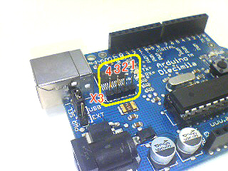
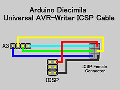
Connect the pins of X3 and the pins of ICSP by wires. Please see the photograph below. (click to enlarge)
- Connect Diecimila and a PC by a USB cable.
- Run the avrdude-GUI.
- Read the Fuse-bits.
- Click on the [Read] button of Fuse area.

- If the fuse-bits are read, it is working.
When an error is displayed, it is not working. confirm wiring and setting of avrdude-GUI.
- Run it by fast clock mode.
- Delete "-B 4800" of Command line Option area.

- Read the Fuse-bits. again.
If the fuse-bits are read, it is working by fast clock mode.
- Burning the bootloader.
- Set the new ATmega168-chip.
- Discconect USB-cable from the Diecimila.
- Remove ATmega168-chip from the Deicimila-PCB.
- Set the new-chip onto the Decimila-PCB.
- Connect USB-cable to the Diecimila again.
- Writing the Fuse-Bits.
- Set slow clock mode.
Key in "-B 4800" to text-box of Command line Option area.
Attention !!! A virgin chip cannot run by fast clock mode.
- Erase
(1) Click on the [Chip Erase] button.
(2) Click on the [Read] button of Lock Bit area. The value 3F of Lock Bit should be displayed.
- Writing the Fuse-Bits.
(1) Set the fuse-bits as below. (These settings are for only ATmega168.)
hfuse = DD
lfuse = FF
efuse = 00
(2) Click on the [Write] button of Fuse area.

- Switch to fast clock mode.
Delete " -B 4800" Command line Option area. And read the Fuse-Bits.
When do not read the fuse bits, probably, you had a mistake to set the Fuse-Bits. Return to slow clock mode. And write the Fuse-Bits again precisely.
- Preparing Bootloader hex-file.
- Click on the of the Flash area.
- Open the "C:\Program Files\arduino-0013\hardware\bootloaders\atmega168" folder.
- Select "ATmegaBOOT_168_diecimila.hex", and click on the [Open(O)] button.

- Burning
- Click on the [Erase Write Verify] button of Flash area.
- Wait until this working will be finished.

- Writing the Lock-Bit.
- (1) Set the Lock-Bit as below.
Lock = 0F
- (2) Writing
Click on the [Write] button of Lock Bit area.

With the above burning of the bootloader is the end.
If you want to burn the bootloader onto .....
-
ATmega8 [Click here]
at ATmega8: Use these fuse-bits and lock-bit.
- hfuse = CA
- lfuse = DF
- unlock = 3F
- lock = 0F
About lock-bit,
http://arduino.cc/en/Hacking/Bootloader says unlock = FF, lock = CF. That is wrong in this method.
Information from Mr. RV Prakash. Thanks.
-
ATmega328P [Click here]
Download avrdude.conf (Update: it's included chip-parameter of ATmega328P)
Use these fuse-bits,lock-bit and .hex file as follows. (according to arduino-0013\hardware\board.txt)
- hfuse = DA
- lfuse = FF
- efuse = 05
- unlock = 3F
- lock = 0F
- bootloader .hex file
arduino-0013(or 0014)\hardware\bootloaders\atmega168\ATmegaBOOT_168_atmega328.hex
- Confirming.
- Disconnect USB-cable form the Dicimila.
- Remove the wires of ICSP and X3.
- Connect a USB cable to Diecimila again.
- Push the reset button of Diecimila.
- Start Arudino-IDE
- Upload sample sketch "Blink".
And it will be run.
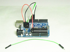
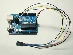
- Dicimila become AVR-Writer
We can use Dicimila as an universal AVR-Writer if we use avrdude-serjtag,avrdude-GUI and the ICSP cable such as the photograph below. (click to enlarge)
Thanks
Very thanks Mr.Suz who developed BitBang Mode AVR-Writer software "avrdude-serjtag", and Mr.Yuki who developed GUI-wrapper of avrdude.exe.
Links
avrdude on FT245R/FT232R by Suz AVR-Research --> (Translation to English by Google)
avrdude on FT245R/FT232R(Linux) by Suz AVR-Research
-->(Translation to English by Google)
FTDI Drivers for avrdude in Linux by Coffeebot Labs
avrdude-GUI (yuki-lab.jp Version) --> (Translation to English by Google)
BitBang Mode AVR-Writer on Mac --> (Translation to English by Google)
[Another Hack]
Arduino meets Processing via WiFi. How to make cheap WiFi environment for Arduino by FON's router.
[Return]
update 2009.03.20 avrdude.conf (update on 03.18 failed. update again)
update 2009.03.19 about ATmega328P
update 2009.03.18 avrdude.conf (add device data script for ATmega88P,ATmega328P)
renew 2009.03.07
update 2008.11.07
upload 2008.07.27 05:48(JST)